
 EyeTrackVR Docs
How to assemble a V5 Pro LED hardware kit
This guide covers the V5 Pro LED Dev kit. The kit uses one USB-C mainboard, six standard V5 LED boards, two V5E end boards, and various two-wire cables.
Buy the V5 Pro LED Dev Kit from the EyeTrackVR Store.
View the V5 Pro PCB source files on GitHub.
Disconnect power first
Do all wiring with the USB-C cable disconnected. Recheck every connector before applying power.
Identify the parts
Mainboard
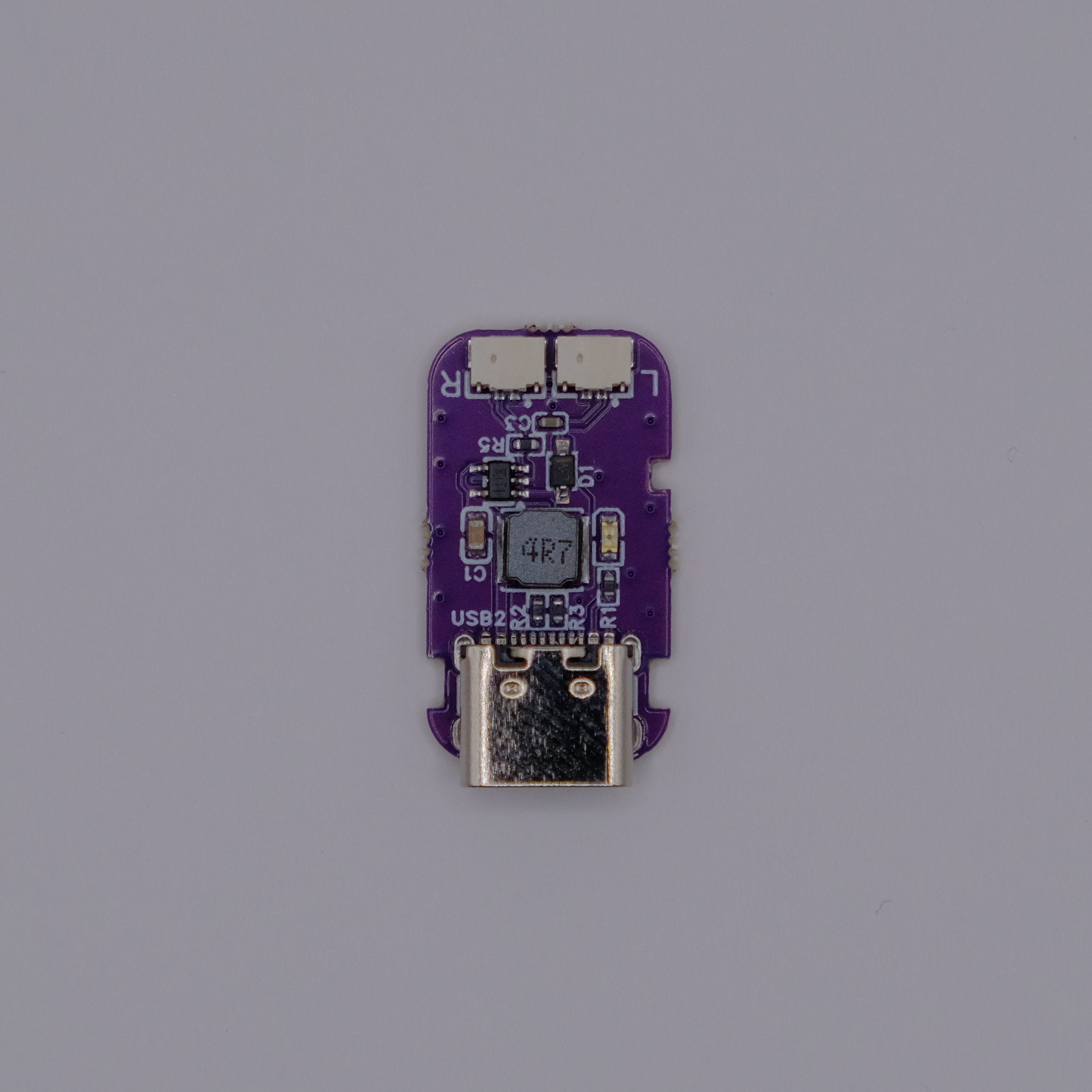
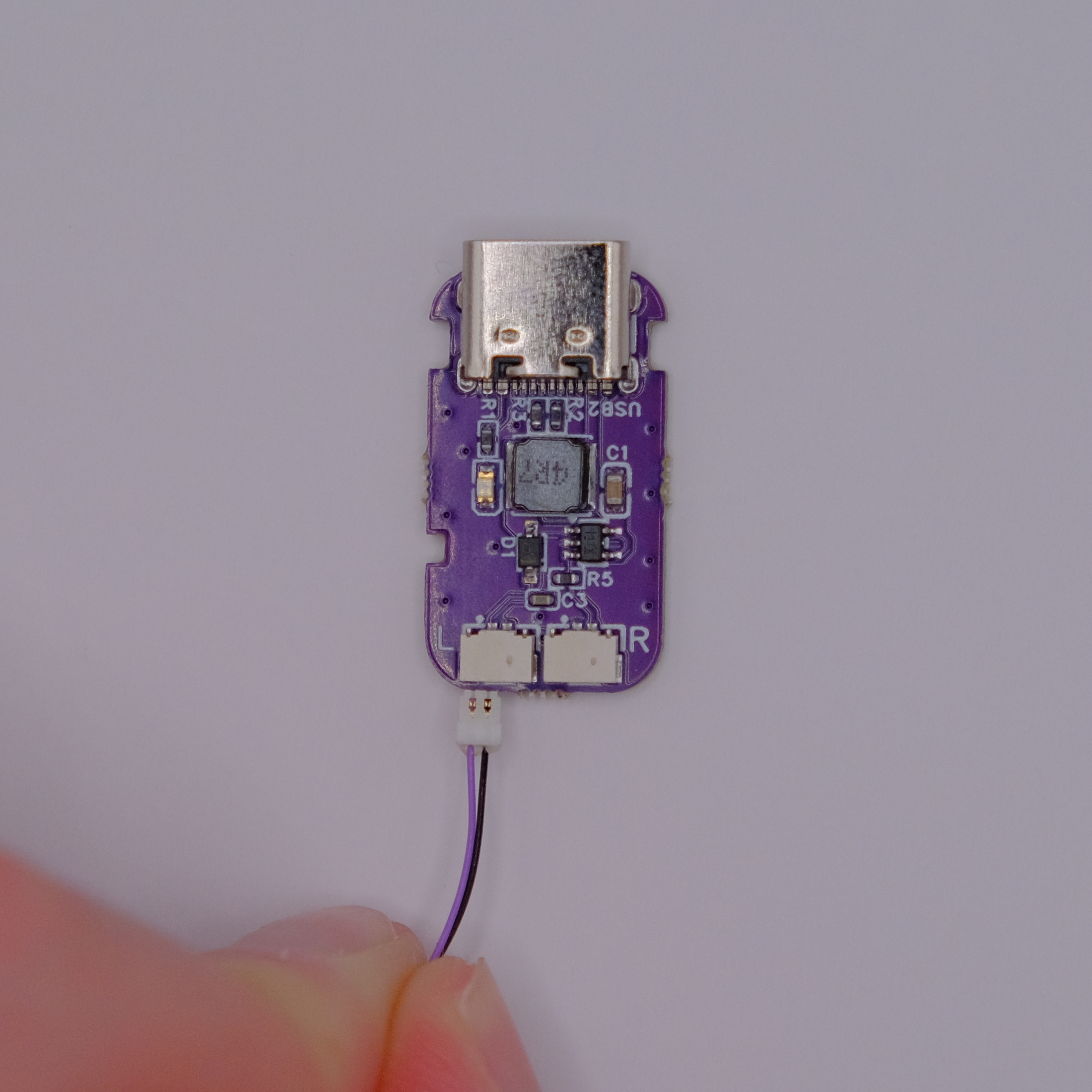
The V5 mainboard has two LED outputs. With the component side facing you and the USB-C port at the bottom, the sockets are marked R for the right eye and L for the left eye.
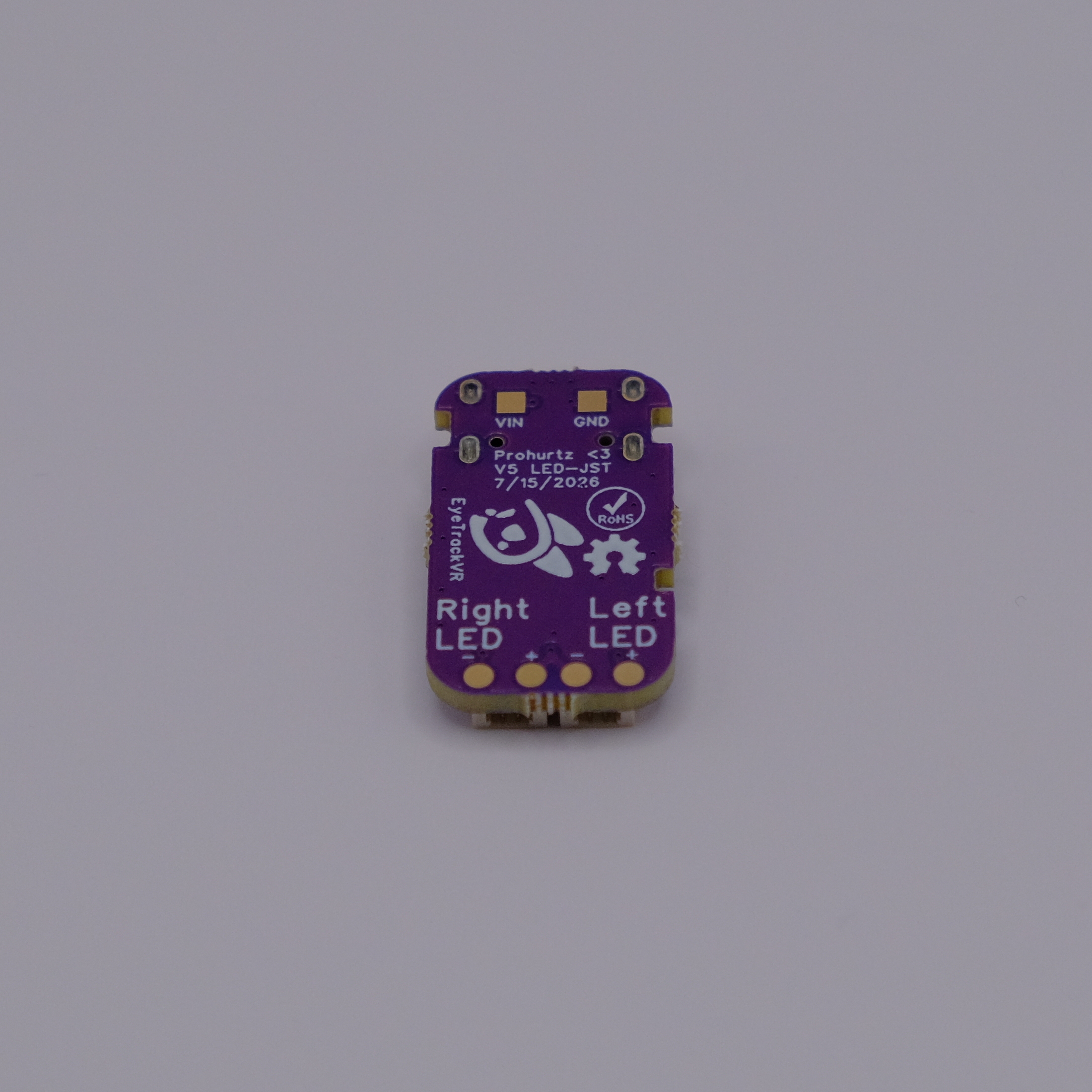
The back is labeled Right LED and Left LED. Use these labels to choose the correct socket. Do not rely on where a socket appears in a rotated photo.
LED boards
Each eye uses three standard V5 boards and one V5E end board. The two types are very similar, so identify them by the marking on the LED side of the board as well as color difference (E is Purple).
Standard V5 board (three per eye)
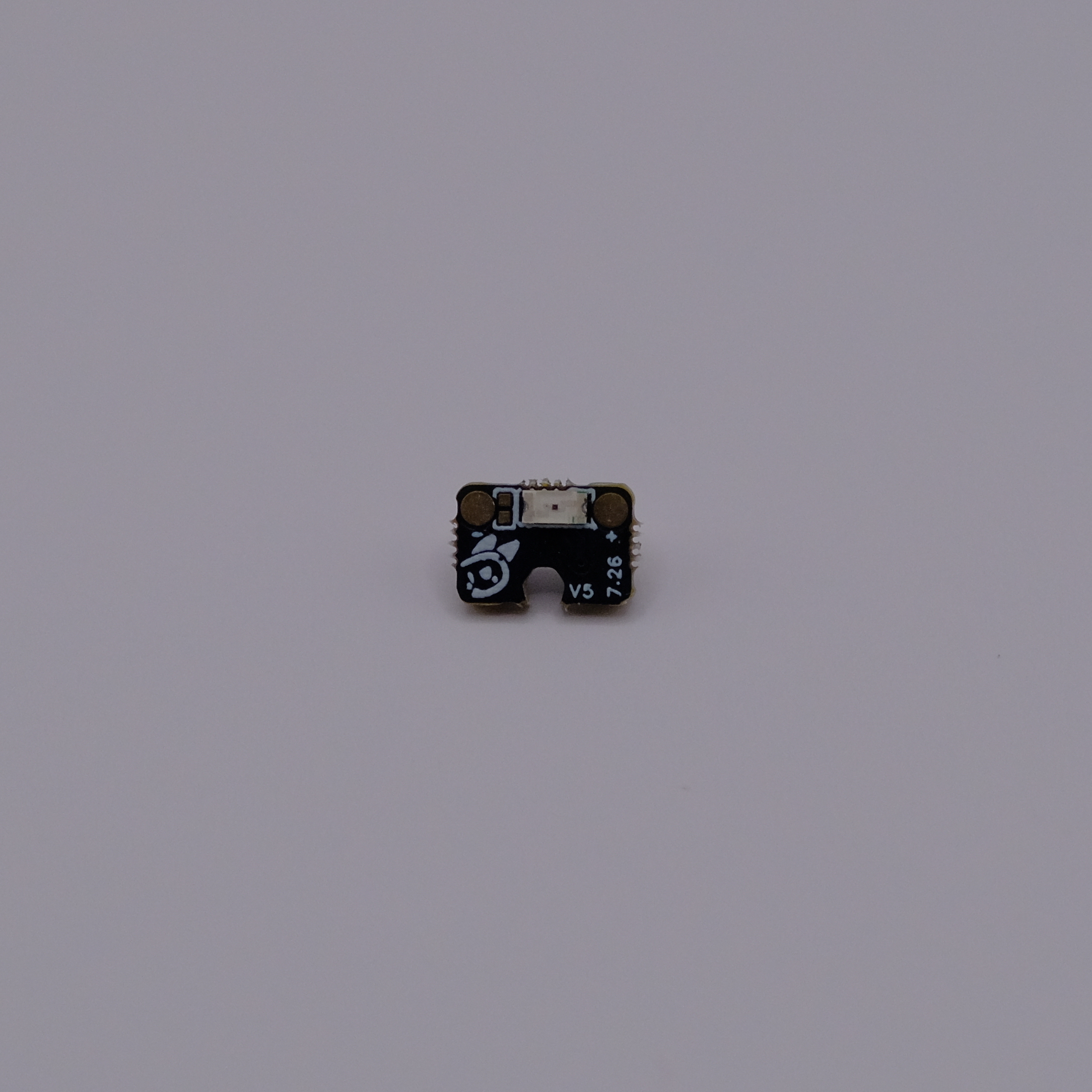
A standard board is marked V5. These are the first three boards in each eye's strand. Each one connects to the next board.
LED side: the V5 marking is visible.
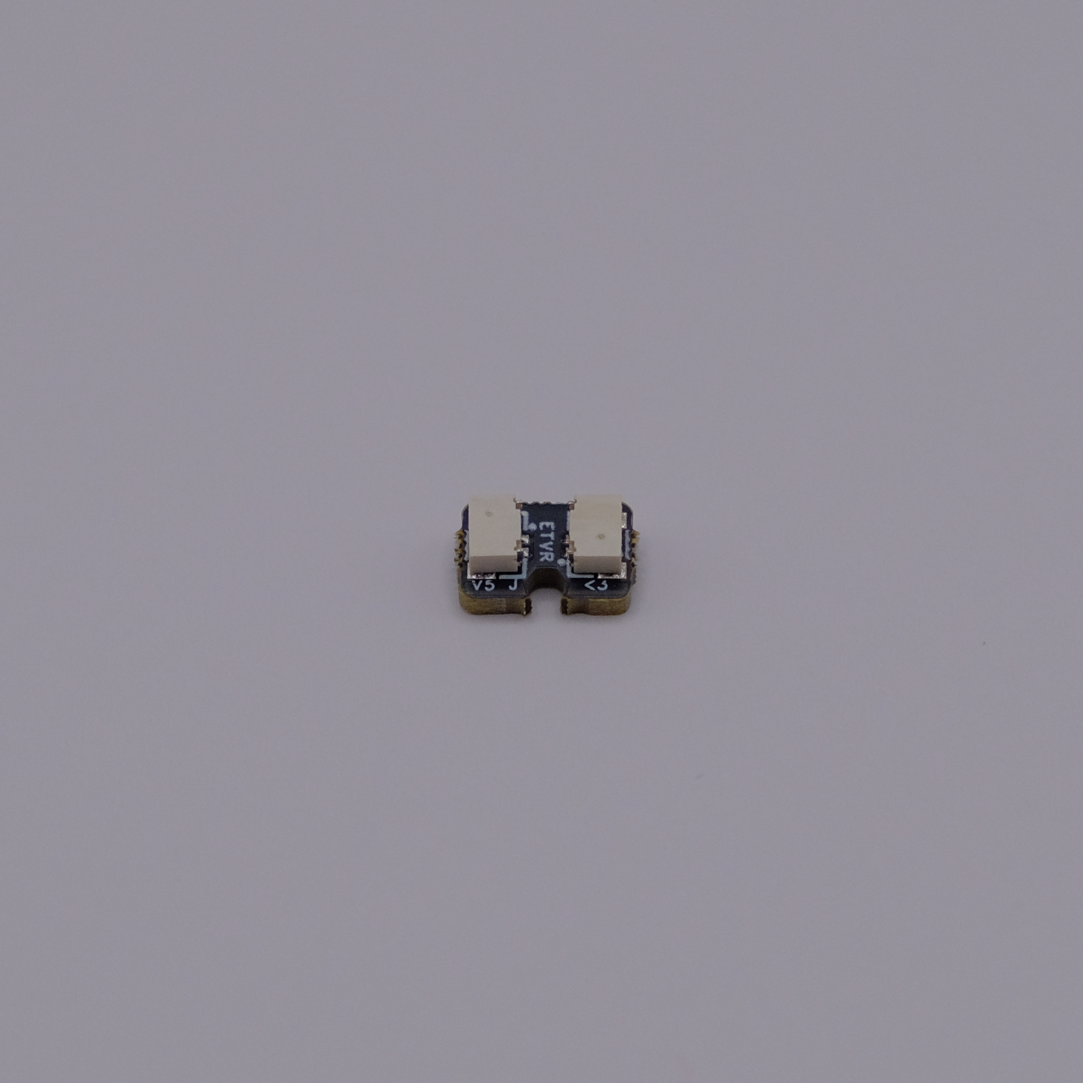
Connector side of the same standard V5 board:
End V5E board (one per eye)
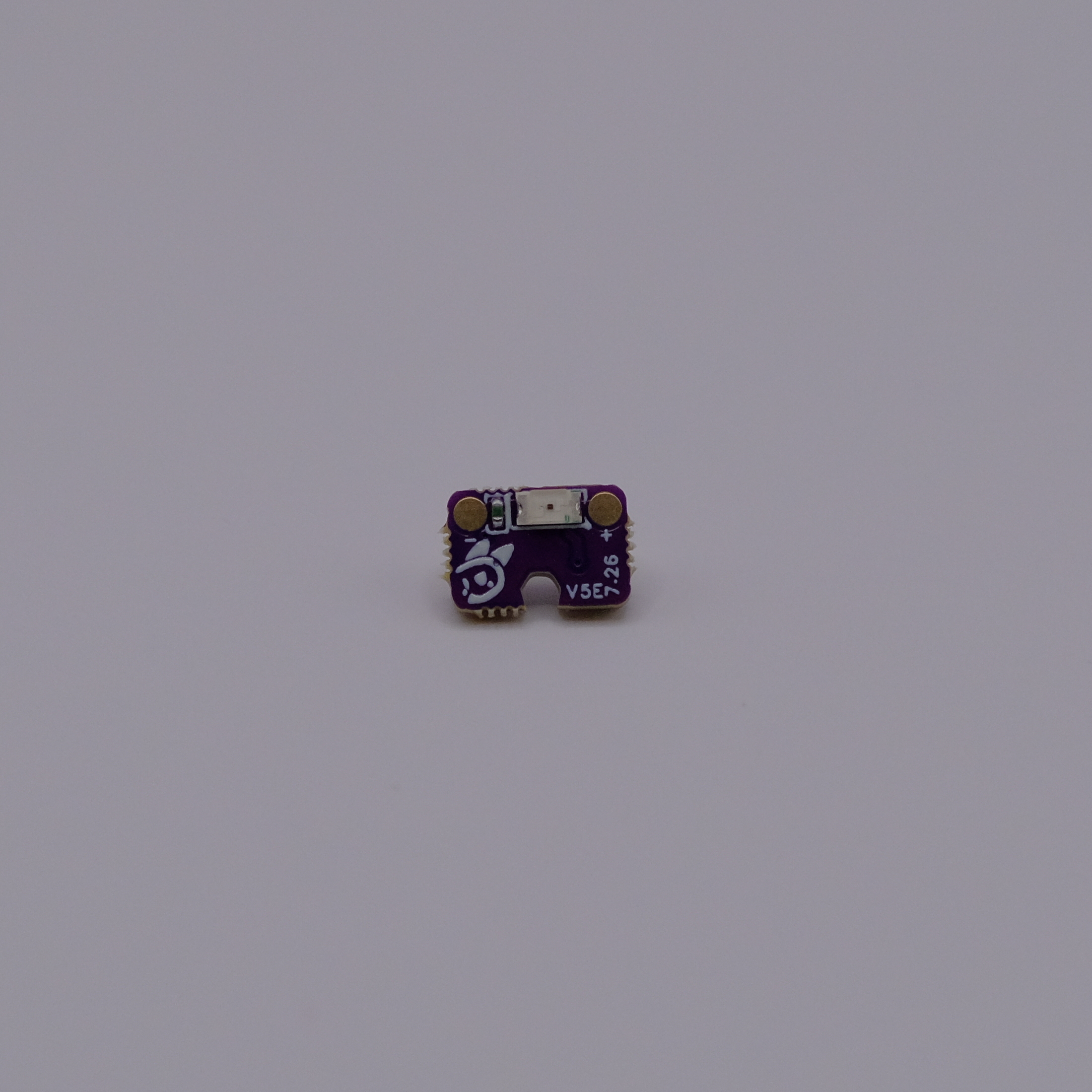
An end board is marked V5E. It must be the fourth and final board in the strand, farthest from the mainboard.
LED side: look for the extra E in the V5E marking.
Connector side of the same V5E end board:
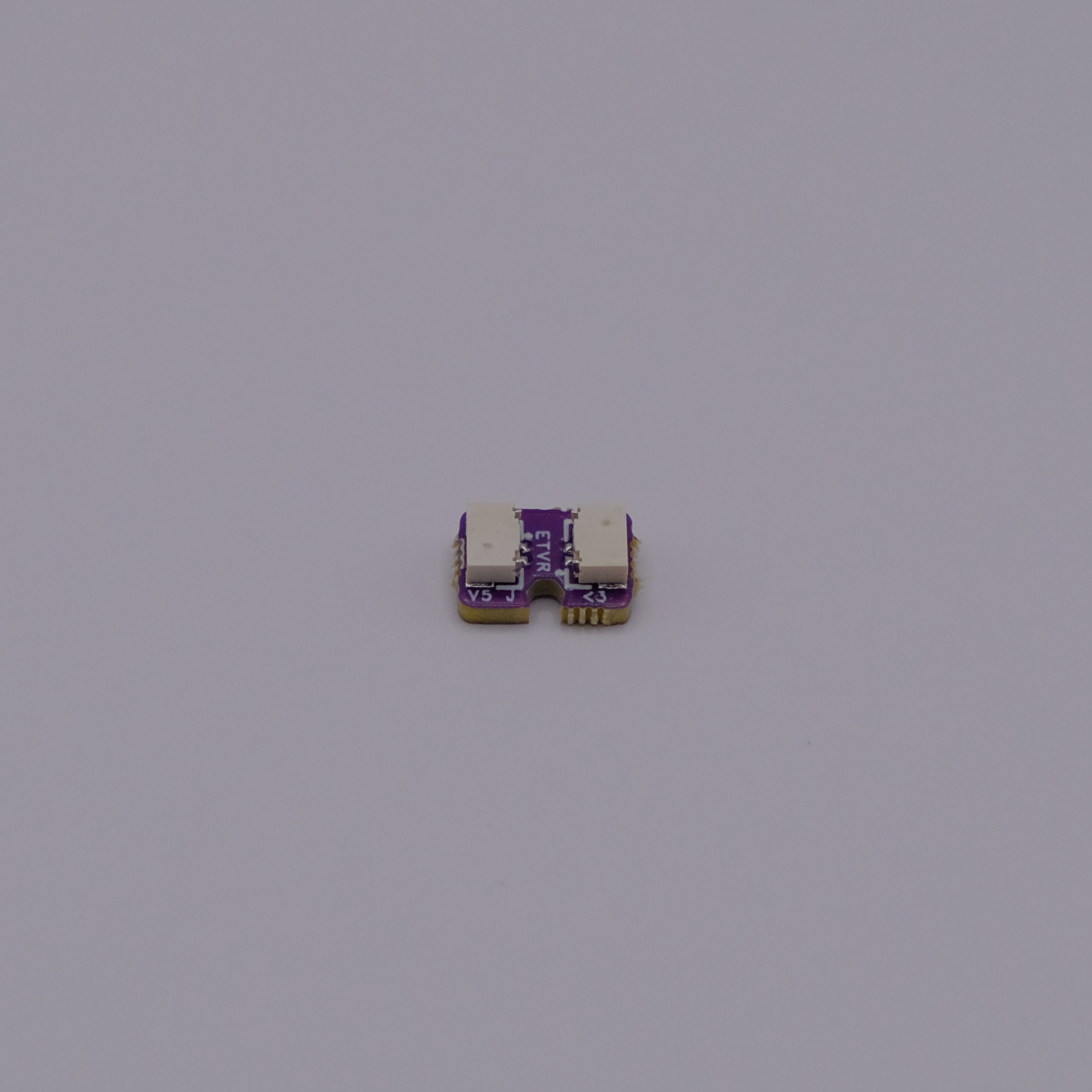
The reliable identification check
The connector sides look similar. If you are unsure which board you have, turn it over and read V5 or V5E next to the LED.
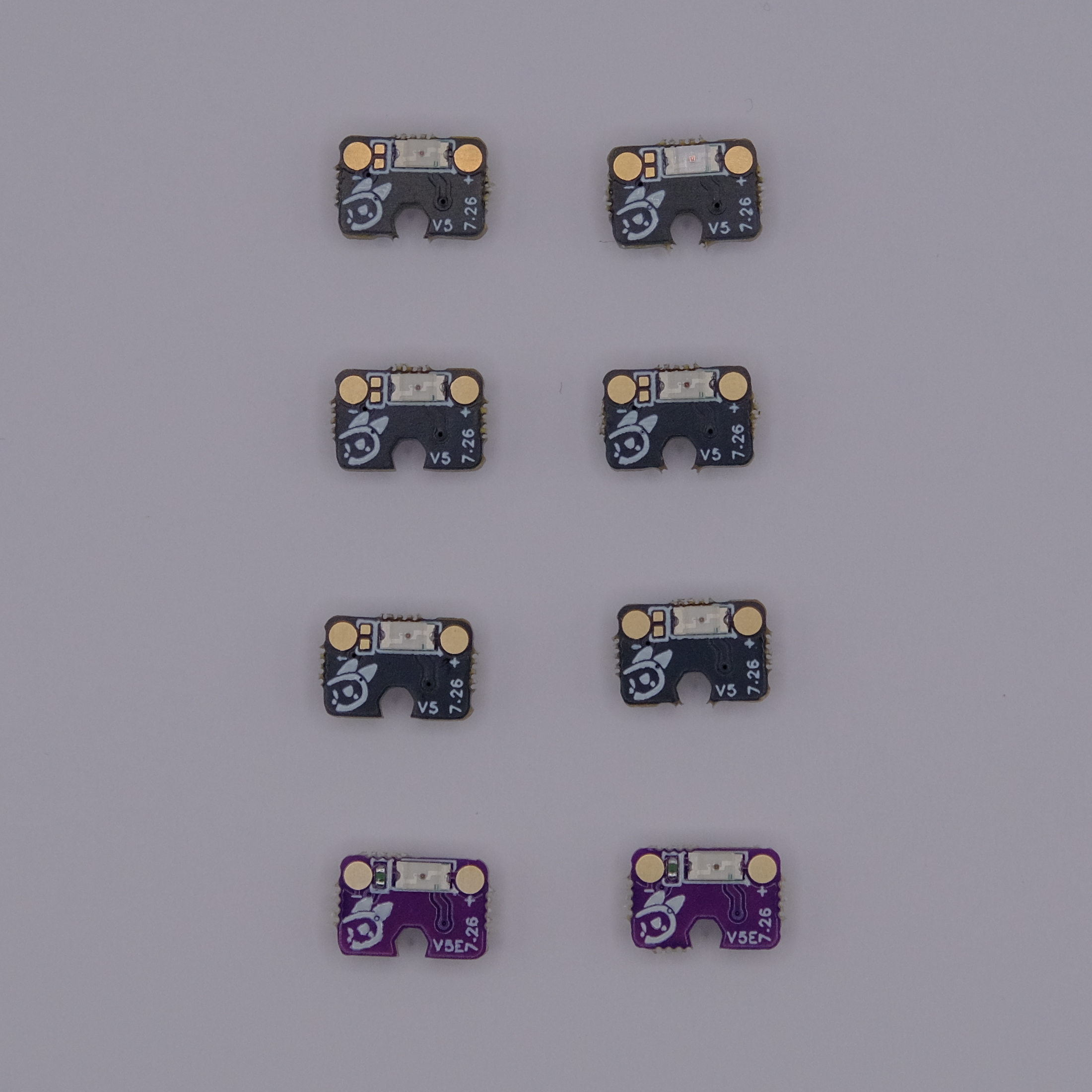
The complete kit contains six V5 boards and two V5E boards. Check the printed markings and board color.
Cables and keyed connectors
Here are 6 "Short" wires typically used between LED and LED.
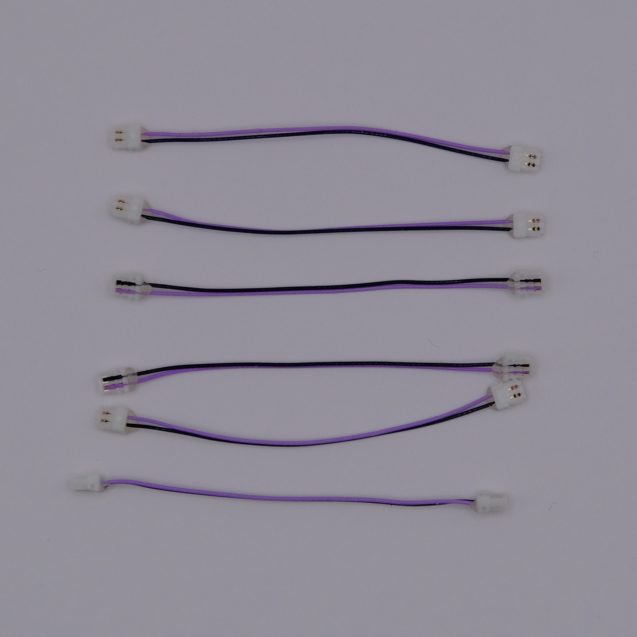
The connectors are keyed
The two-pin connectors are keyed and normally cannot be inserted backward. If a plug does not go in easily, stop and check its direction. Never force it into the socket, although they may take some force to plug in. Double check if unsure.
Unplug cables by pulling. Do not use tools
To disconnect a cable, pull both wires together and straight out from the connector. This is safe, and the cables are designed for it. Do not pry at the plug with pliers, tweezers, a screwdriver, or other tools. Tools can damage the small connector. Before pulling, remove any glue or anything else that would stop the plug from coming out normally.
Assemble the two eye strands
Build the left and right strands separately. The order for each eye is:
mainboard output -> V5 -> V5 -> V5 -> V5E
This means the completed dual-eye kit has two four-board strands:
| Eye | Mainboard socket | Board order |
|---|---|---|
| Right | R / Right LED | V5 -> V5 -> V5 -> V5E |
| Left | L / Left LED | V5 -> V5 -> V5 -> V5E |
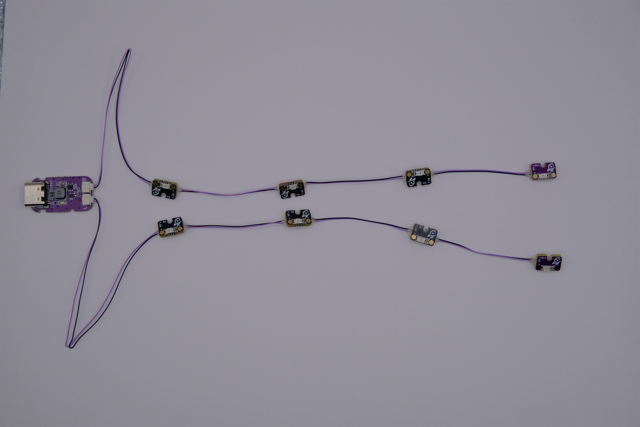
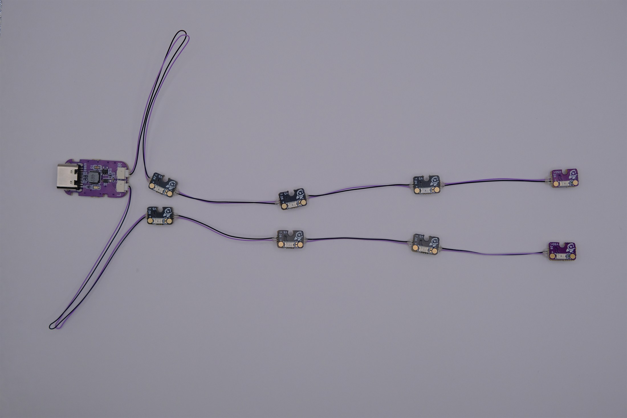
Use the following completed assemblies as wiring references. They show the two correct configurations for the V5 kit. The board orientation and cable routing differ slightly, but both use three V5 boards followed by one V5E board for each eye.
Note the LED board orientation in how they are plugged in. Be careful as a wrong orientation will cause it to not work.
Correct assembly example 1:
Correct assembly example 2:
If your headset mount needs more distance at the end of a strand, you may use a longer cable between the third V5 board and the final V5E board.
1. Connect the mainboard ends
Connect one long strand cable to R and the other to L. In the photo below, one cable is connected to the R socket.
2. Add three standard boards to each strand
Starting from each mainboard cable, connect three boards marked V5. Connect the mainboard cable to the first board, then connect the first board to the second and the second board to the third. Following the oreintation shown in the working setup examples above.
Before plugging in each connector, check these three things:
- The board is marked
V5, notV5E. - All three boards face the same direction and match the chosen assembly photo.
- The plug is straight and lines up with the socket. No pins are bent or sticking out.
3. Finish each strand with a V5E board
Connect one board marked V5E after the third standard board in each strand. The V5E board is last, so nothing connects after it.
Check the orinetation to be correct compared to the exampels above.
Final check and power-up
Before connecting USB-C, check both strands from the mainboard outward:
Rfeeds exactly threeV5boards and then oneV5Eboard.Lfeeds exactly threeV5boards and then oneV5Eboard.- Every plug is pushed in all the way.
- No exposed metal can touch the headset or another board.
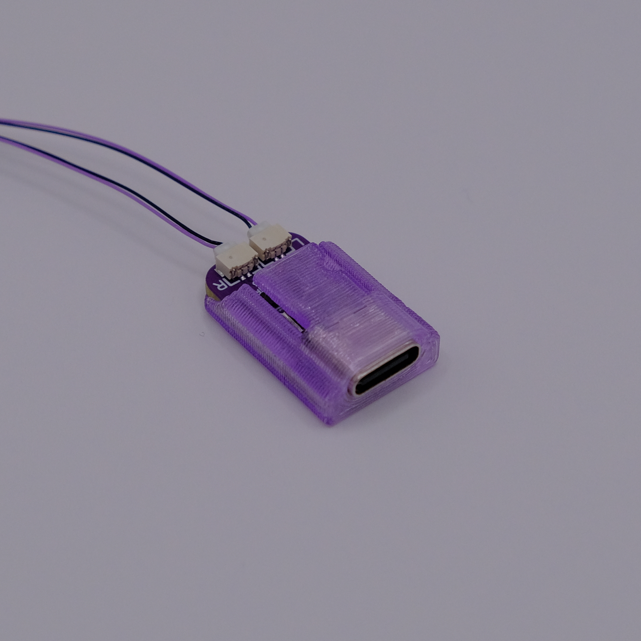
The mainboard can then be installed in its printed housing. Keep both LED cables clear of the case edges so they are not pinched when the housing is slid on.
Insert the PCB and slide it into the 3d print. Note this may take some force, be careful but its okay to push it!
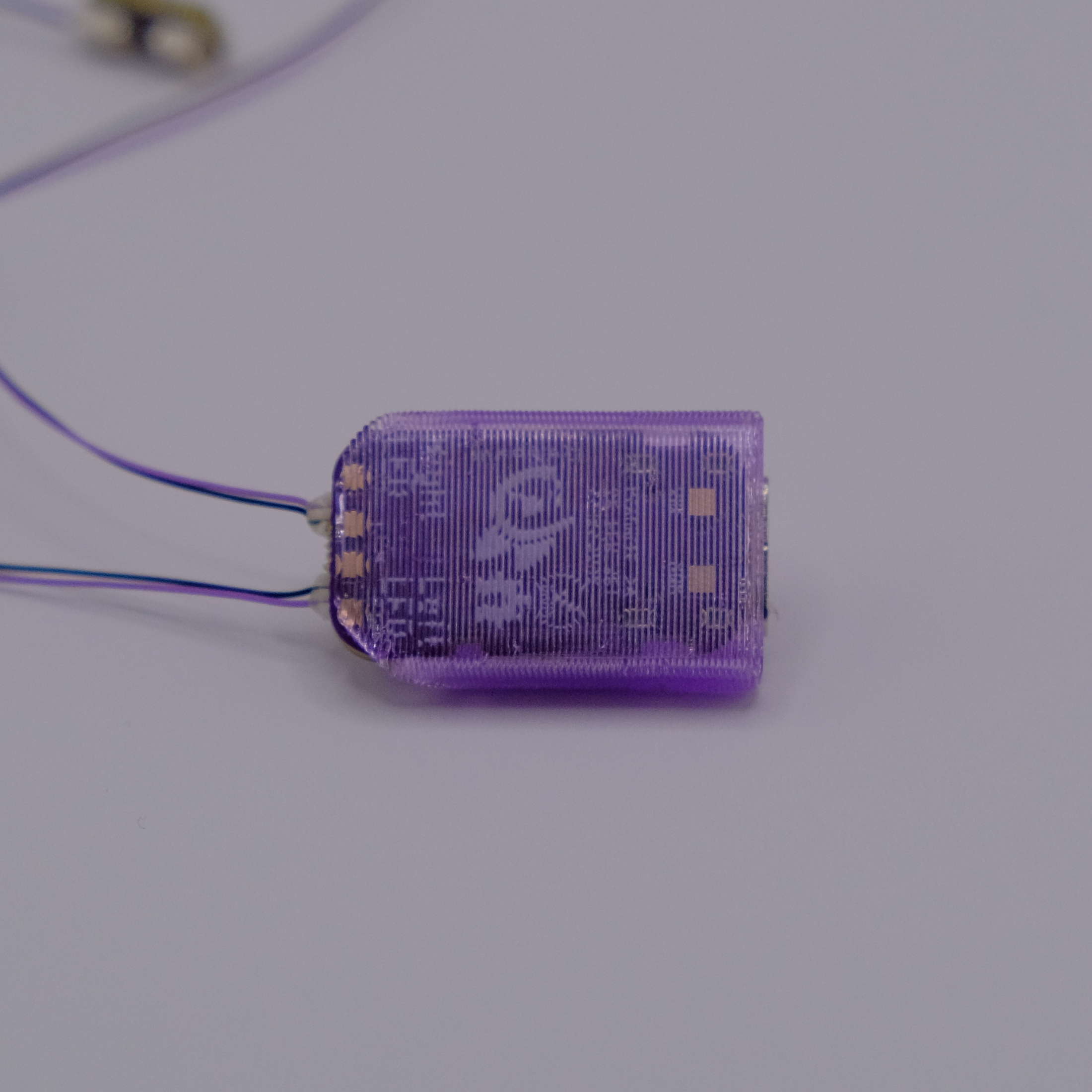
Connect USB-C only after completing the inspection above.
Optional sweat protection
Most people do not need additional sweat protection. If you sweat heavily, you can apply a thin layer of clear nail polish to the board around the LED and exposed pads, but not on top of the LED lens.
Before applying it:
- Assemble and test the entire kit until it works correctly.
- Disconnect USB-C and all power.
- Keep nail polish out of the wire connectors and away from connector contacts.
- Let the nail polish dry completely before reconnecting power.
Do not use superglue
Do not use superglue on or around the LED boards. Superglue can damage the LEDs permanantly.
FAQ
Help! No LEDs light up
Infrared light is invisible to the human eye. Check the LEDs through a phone camera or an ESP camera to confirm whether they are on.
If no LEDs appear through the camera:
- Ensure every connection matches one of the two example eye strands shown above.
- Check that every connector lines up correctly and is pushed in all the way.
- Restart the mainboard by unplugging its power cable and plugging it back in.
- Confirm that the orange LED on the mainboard is on.
The mainboard has no orange LED
Try a different power source, such as a computer, battery bank, or USB wall adapter. Also inspect the mainboard and LED boards for physical damage.
Help! I'm missing a part or it isn't working
If an important part is missing or the kit still does not work after completing the checks above, email support@fovea-labs.com. We will do our best to make it right.